Electronics DIY blog

DIY is fun and is food for the brain and spirit. Don't be afraid to learn.


Showing posts with label CNC. Show all posts

Thursday, August 27, 2015

Building a CNC - Frame modifications and (re)assembly

Now for the frame.
First I had to fix a construction misalignment (explained in the picture bellow), that caused the the stepper motor axis to collide with the linear rail bar and twist and rotate eventually breaking the coupler in two.
I did it by cutting the corner stuffing (inside the cutted tube and over the corner) a metal bar that I had laying around (and was pretty much the height I needed), and then weld it and cut it to the desired length. The picture gives a clear idea. The fact that the bar entered in the tube also acted as an reinforcement. I was quite happy with the result.
Modifying/fixing the rail angle

One other thing I didn't liked in the initial design was the bottom bars in the frame. The initial idea was to put the bottom plane over these bars. But any millimetric offset would mean that the "floor" of the CNC would be like bump or a dip. So I removed the bars, used them to reinforce two of the sides (for the axis that clamps on the top side. The bottom side would probably cause collision problems) and the corners in the bottom square.

Modified Frame
 To finish I gave it a black paint cover and the axis a red tone as you can see bellow.
After the paint job
Finally I reassembled the CNC and gave it a spin. It's a working machine. OHHHHH YEAHHHH.
The picture bellow was taken before all electronics were in place but the machine is all now fully loaded and tuned.
Assembled Axis and Frame


Now I must thing of a name for my baby/beast CNC..hummmm
More modding is on the way. Electronics are next. So stay tuned...

Friday, August 7, 2015

Building a CNC - X and Y axis modifications

I've been working on changing some less well thought/crafted parts.

The way the RM1605 ballscrew thread was mounted/fixed on the X and Y axis was one of them. The fact that I was depending on some rubber pads to align it with the stepper motor shaft was not ideal and was a source of alignment issues.

To fix that, I rotated the BK and BK block by 90º, so it would stand on it's side. These block are 60cm wide (aprox. the same as my NEMA23 stepper motors) and allowed an almost instant misalignment free position.

Here is the new supports welded to the X axis.
New supports

X-axis fully assembled

To be continued...

Monday, March 9, 2015

Building a CNC - The end (a new beginning)

After a 8 months break I restarted to think on my CNC and the away I could put this puzzle together since I didn't thing the design all the way through.
It toke me about 4 hours to come up with a plan the result was a working CNC :-P.

I actually had to undo a couple of parts I have showned in past posts, and replace others. To make the last parts and since no welding was needed, I used aluminium rectangular tubes (easier to work with).
I've also relocated all the electronics to an old Pentium II PC that I had laying around, and now have a neat single tower PC/Controller solution that I will also show.
In the next posts I'll try to show what I've done to assemble the CNC, what I've accomplished in terms of results, and some of the problems I've encountered and I'm currently fixing/working.

To be continued...


Friday, February 7, 2014

Building a CNC - Improving backlash in cheap chinese RM1605 (ball bearing threads)

I've been struggling to get the CNC moving but the time and place are just not there.
I just needed some time off to finish this but I won't get any time soon so...

In these dead times I've been studying the BF12 block of the ball bearing threads.
This comes with a lock nut but when I use it it rubs against the rubber seal which causes a lot of friction and makes the stepper motor life harder.

BF12 bearing thread block

So to do if I can make something of it I disassembled the BF12 block. OHHH MMYYY GGOOODDD. Has expected this was poor pissed machined. This is what you get when you buy cheap Chinese crap. Just lock at the state of those two screws in the photo. The thread is completely worn out, because the holes where misaligned. The problem that causes the rubbing is the size of the spacers (bellow the ball bearings) that are just to short.

BF12 block disassembled (poor quality chinese product)

The way to fix this is to make a couple of new and longer spacers.
If the hole for the bearings is too deep (resulting in unwanted space and backlash) there is an additional method for preloading and it's a cheap and easy trick. Use an useless plastic card and make a washer to put between the bearings.
I'll show the final idea with a drawing:
Existing parts in blue and new ones in red
Preloading forces to ensure near 0 backlash

Now the fabrication part. If you are like me and don't have a lathe (oohh I wish...maybe I'll try to build one too :-P), you have too options.
  1. Pay someone with a lathe to make it.
  2. make a very rudimentary lathe like-thing with a power drill.
Since I don't want pay for this task I'll show you how you can make some lousy crafted (almost Chinese quality like :-P) but usable spacers and a trick to preload the bearing inside the BF12 block.
First the preloading plastic washer. Drill the card with a 12mm drill bit and cut with a scissor to make a crude plastic 1mm thick washer.

Drilling the plastic card

Put them between the two bearing and close the BF12 block again. Has shown in the earlier drawing, the pressure from the front plate will make the outer ring of the ball bearing go in and the washer will make the inner rings go out. This removes the backlash from the bearings.

For the spacers I use the power drill as a crude lathe. I cut a peace of 14x1mm steel tube and put it inside a M12 screw. Next I tight the end of the screw in the drill chuck and turn it on. To remove metal from the exterior of the tube I use the sharp edge of a drill and move it along the tube. I just need to remove about 0,5mm of steel. I finish it with a file and a peace of sand paper. To cut it put a saw against the tube to make an almost perfect perpendicular cut. Size doesn't matter that much. I just have to make sure it's bigger but not too big. And voilá. The new spacer.

Crude lathe in the drill press

Using a drill bit to grind the tube

Using a saw blade to cut the tube in almost straight line

A couple of spacers and a plastic washer


Original bearing in the left and new on the right.
The reassembled bearing thread is now virtually backlash free.
This is solution a-la-Macgyver but it works just good enough...lolol.

Friday, January 24, 2014

Building a CNC - Z-Axis

This week was all about building the Z-Axis frame.

For this one (since it is a lot smaller) I went for a couple of SBR16 linear rail guides.
It's made of two parts:
Z-Axis front plate (left) and back plate (right)
The back plate (smaller plate) is where the X-Axis bearing system is fixed. This is also where the RM1605 ball bearings nut will be attached. The mechanism is similar to the X/Y-Axis interface I built, but instead of two 608-ZZ bearing clamping the rail, this is a single aluminium peace directly screwed to the plate.

The front plate is a peace of metal sheet where both the SBR16 rails and the KF-12 and KB-12 (RM1605 ball bearing screw support blocks) are attached.
The front plate will accommodate the engraving/printing head of the CNC.

Here are a couple shots of the Z-Axis.


I've already made the motor mount support that I will place in my next iteration.
For the paint job, I went for spray paint this time. It is a hole lot better. Easier to apply, thinner layers and more homogeneous coating, and much less time to dry.
I'm actually considering repainting the hole machine, with different colors for the different axis components.

I just wish I had more time to finnish the machine. These lunch hour builds are 50% working and 50% preparing and cleaning up. Efficiency killing...

Thursday, January 9, 2014

Building a CNC - Y-Axis - part 4

Finally some progress.
I've been working on the movement transfer interfaces between the CNC arms.
This is the binding element between the X and Y axis.

I've made it with some pieces of rectangular tube aluminium profiles from my previous CNC.

Here are all the elements individually.

X-Y arm interface

The larger holes where made with a circular drill bit.

I've made 4 spacer also with aluminium tube. These spacers will keep the structural shape of the rectangular tube when I tight the nuts that hold it in the ball bearing nuts.

Here are a couple of shots that show the assembly of the X-Y interface piece.


Monday, October 28, 2013

Building a CNC - Y-Axis - part 3

Yesterday, I started mounting the Y-axis ball bearing transmission to the arm.
First I had to deal with the transmission block vs stepper motor shaft difference of heights.

To address this situation I used an 0,80€ pencil rubber that I sliced to act as anti vibration pads beneath the linear transmission blocks. It's cheap and it does the job well. I'm hoping it will help me cope with the noise caused by the vibration of the steppers running, against the steel structure.


Next I made a steel plate that will act has the stepper mount plate, and weld it against the arm.


But when I mounting the arm in the CNC cage ...WTFFFF...
The ball bearing thread hits the linear rail of the Z carriage.
Fortunately I only made alignment welds. I had to cut them put the rails of the Y arm higher and re-weld them into place.

Has you can see there is now a very small gap between the Z-rail and the Y-thread, but I should suffice.
To be continued...

Wednesday, October 23, 2013

Building a CNC - Y-Axis - part 2

Here is an update of my CNC building.
Has I stated before I'm doing this in my lunch break. This resumes to 30 min. a day. It's starting to feel more like never ending story... :-P


The second arm (Y-axis) is in place and painted (don't mind the onions on the table....:-P)

CNC with X and Y axis arms mounted
If you remember part 5 of this build, you will notice that this arm is some parts short (the smaller 4x 10cm tubes). Initially I welded them, but if you remember by sketch these were not planed. Because of that if I make de Y-axis in the same manner I did the X-axis the bearing thread system + Stepper will not fit.
So I had to un-weld the hole thing. Even without these, the space to fit these components is very very tight. Let's see if I don't have to do any more changes.

This is the Z-axis linear guide bed mount (the start of it at least). This is actually the second one. I'm building this in the dark (it's all in my head. I've not sketched this or made any pre-measures). Because of the way the bearings and the metal sheet is welded the tube with the off-center holes is the one to be welded. Not the other way around. This is to avoid contact between the bearing and the metal sheet.
Z-axis linear guide bed mount build
It would be best if I just pre draw all in Sketchup to see if it fits. And I probably will. Other wise I will make a lot of mistakes in the way. We will see how it goes.

Fingers crossed...

Thursday, September 26, 2013

Building a CNC - Paint job

Last couple of days I've been sanding and painting the frame and the X-axis to delay corrosion (yes delay...not stop...I don't have the means to do it, but this should suffice since this is going to be indoors). This is the handicap of using regular steel instead of stainless steel for the structure. The good thing is that I will do my hole CNC structure for 40€ worth of steel instead 120€ (or a lot more) in stainless steel.

The painting is quite a tedious task but it's got to be done and that's it.

Here are a couple of shots of the painted pieces.
Sorry for the quality of the pictures but I had almost no day light and my phone does not come with flash.

CNC frame box

CNC X-Axis
Cya...

Tuesday, September 24, 2013

Building a CNC - Y-Axis - part 1

Has I said yesterday today I started building the second arm for my new CNC.

I pre fabricated most of the parts yesterday. So today was about making the remaining parts and assemble them all.

CNC Y-axis arm (pre-fabrication stage)

CNC Y-axis assembled arm (almost completed)

I'm almost finished on this one. I kind of gained some speed because this was almost a question of reproducing a similar X-axis arm with some small changes.

I also painted the X-axis that is completed (forgot to take pictures of that one but I'll show that one tomorrow).

This is going smooth so far but I'll start at work again tomorrow so I'll be back to 20-30 min. construction frames in my lunch time. :-(

Let's see how it rolls from here.

Monday, September 23, 2013

Building a CNC - X-Axis - part 3

Okay.

After a couple of well deserved vacations I'm burning my last two holidays to try to advance has much has I can on my brand new CNC.

Today I got to pre mount the ball bearing thread and motor so I could weld the supports for the thread blocks.
I all fits very nicelly.
Here is a picture.

Pre aligned transmition thread and stepper motor
This one is almost ready for the paint job to avoid runsting.
I also fabricated almost all the necessary peaces for the other arm so I thing tomorrow I can complete the second arm as well.

Lets see how tomorrow goes.

Thursday, August 29, 2013

Building a CNC - X-Axis - part 2

As promised here is the reference side of the axis full mount.
Like I said in my early post the dimensions of my linear guide forced me to make a small change  to be able to properly clamp the linear guide bearing to the rail.
Here is a couple of self explanatory photos.

Clamp tube

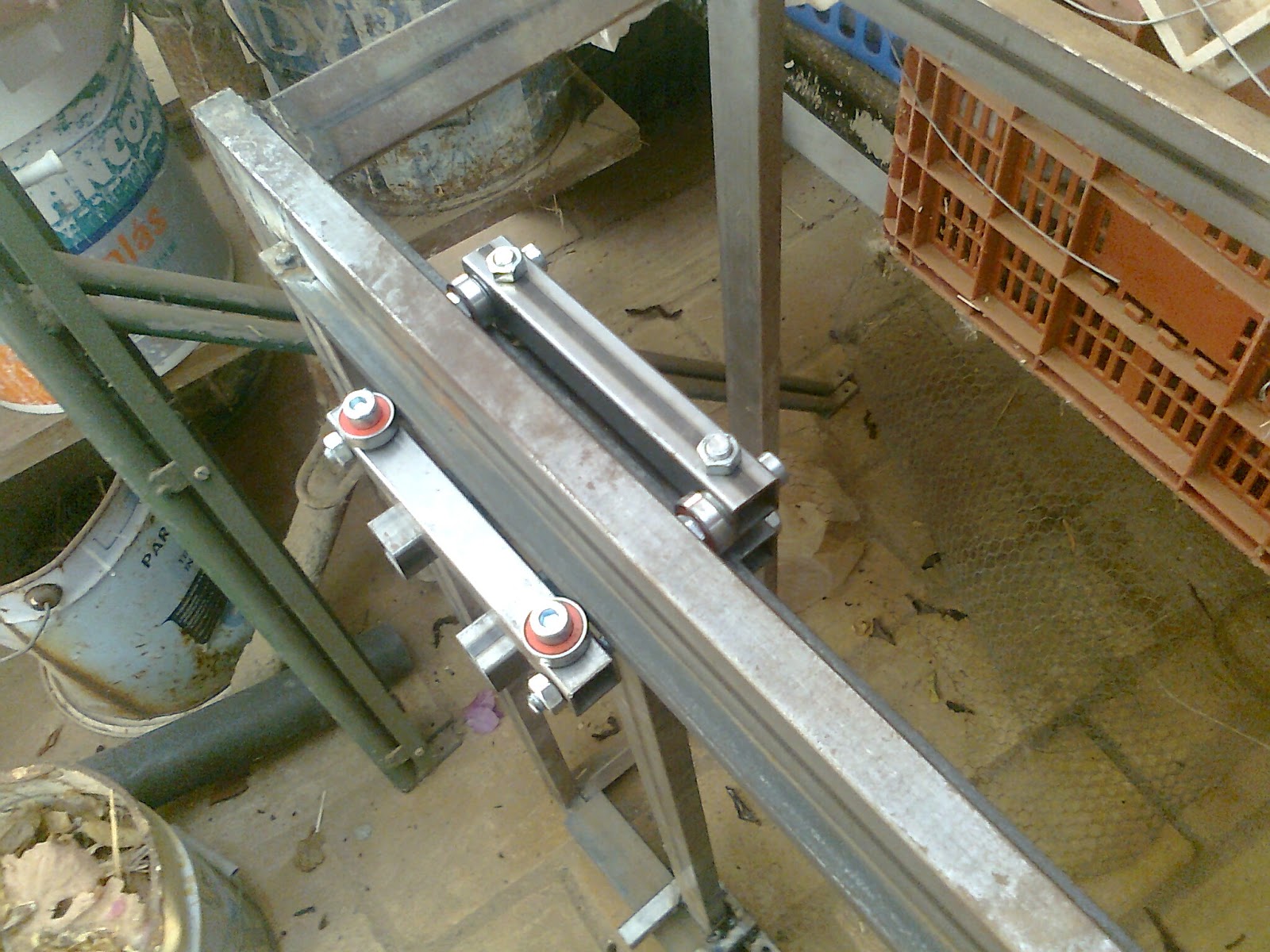
Axis fixed side linear guide block fully mounted
Has you can see, the this forms a claw like bearing system that holds the axis in place.
Here are also a couple of shots of the arm in position.

Fixed linear guide mounted in the rail

Fixed linear guide mounted in the rail (down side)
This linear rail slides very well. Since the steel bar (ruler) that acts like the linear rail guide has a orange peel kind surface it's not as smooth has I would like but I believe it will become smoother in time.

Now to the other side of this axis. This will be quite easy and fast. That side will have a much simpler kind of bearing system to allow some level of structural distortion. I count on having it done tomorrow.

Hurray :-) ...

Wednesday, August 28, 2013

Building a CNC - X-Axis - part 1

So here are a couple a shots for the latest developments of my newest CNC machine.
I'm almost finishing the linear rail guide for one of the arms.
Like always some adjustments are needed.

Axis arm with linear guide supports welded


For example the rail guide bar is 8mm thick. That did not allowed me to put the spacers in the threaded rods that hold the bearings. After some evaluation I will need to redo one of the tubes that holds the bearing with an offset so it can clamp to the rail guide, and hold the arm in place (this is the side that locks the arm in the axis the other will be free to avoid misalignment errors).
I'll explain it better in my next post with the finished arm. For now this just shows a general aspect of the CNC horizontal axis arm.


Linear guide partial mount and testing

Expect to finish this arm soon.
Cya...

Monday, August 12, 2013

Building a CNC - Structure frame

So I've started building the new CNC with some steel tubing.
My welding technics are far from perfect but I think I can get the job done.
Here are a couple of shots from the structure. I have a few welding points to make to reinforce the structure but it's quite solid has it is. I can stand on it and it hold good.


So far I've made the cage frame and I'm starting to build one of the arms. I still have a lot to go before this monster starts moving.

Progress is slow but it is rolling...

Thursday, July 18, 2013

Building a CNC - The start - Conceptual design

I've been cooking this idea for quite a while now.
A brand new CNC.

With Crappy CNC still in the "hospital", I've started to plan a new CNC trying to improve all the previous faults of Crappy.

Better rigidity.
Cheaper materials.
Less axis alignment issues.
Build with accessible tools.

I'm leaning towards a Momus CNC similar design with some dramatic changes.
Here is a partial sketch of Crappy 2. Has you can see the main difference between the Momus and this one is the crossed mount free double arm.


The concept is to keep the counter force that causes frame distortions closer to the milling point.

I'm in the building phase right now. but it's being painfully slow.
More updates coming.

Thursday, August 23, 2012

Milling PCB in a CNC - The guide

OK. So here is a little resume of my process to make PCB with my crap of a CNC.

I'm using freeware version of Eagle to make the schematic and board and then I use pcb-gcode plugin to generate the gcode for the milling.

My steps are these:-Make the schematic and board in eagle.
-After all is in place use the Drc tool in eagle to check your clearances. To do this go to the clearances tab of the Drc tool and set all clearances according to this formula:

Minimum clearance = tool width + (2 * safety offset from pad/via distance)

Why?
Because using the same formula in the pcb-gcode plugin will allow you to make the PCB using 2 passes (making a PCB in a single pass doesn't always ensure proper isolation and almost always needs deburring and more the two passes is excessive and time consuming). The 2-pass isolation has yield the best results for me with a 10º v carbide bit. I'm still waiting for the 60º bit. I'm hopping it can produce similar results with a single pass. For now I'm sticking with 2.

The above formula is a reference and should be used has a reference only. If overlay occurs it's not the end of the world. The amount of overlay is the problem. Some SMD components might not even comply with the clearances. It's OK. But you should check the generated gcode for those places to see if they where properly isolated.

-Next configure pcb-gcode plugin. If you are going to work in metric units (mm) change the gcode-defaults.h in the setting folder of the pcb-gcode plugin to output the coordinates with only 3 decimal places after the floating point.

This is done by changing this line:
string FORMAT     = "%-6.4f ";      /* coordinate format */

To:
string FORMAT     = "%-6.3f ";      /* coordinate format */

Milling depth = -0.05mm
Remember most copper sheets in raw PCB is 35 microns (0.035mm). 0.05mm should be enough without going too deep.

Tool width = 0.2mm.
In my case I'm using a 0.1mm v-bit 10º. I set this to 0.2mm to compensate for run-out, vibration and bit wobbling (being such a thin bit it bends while trying to remove the copper. It's like forcing a needle to scratch a surface. Bending will occur. Also must compensate for the widening of the tip as it goes deeper.

Default isolation = 0.15mm
this is an other place where you can compensate for all the variables above. I prefer not to do it here. In here I like to put the amount safety margin to apply to pad/via clearance.

Isolation step <= Tool width.

Maximum isolation = Default isolation + Isolation step.
This insures 2-pass milling.

Don't forget to set the feeding speed. I'm using between 60 and 100mm/min. Faster then that bits will brake, deformations in isolation will be produced and you don't want that.

-After a good gcode is achieved It's milling time. Secure the PCB to the table in a way that avoids (un)leveling (usually the PCB is not perfectly flat due to storage conditions).
Two ways to do this.
The pro way. Use a vacuum table.
The cheap and dirty (but totally works). Double side scotch tape. This the one I use. It works (period). Read this.
Home the bit with one of the to procedures I've mentioned in a early post (Eagle2GCode - Part 2).

And you are good to go. You should be ready to start milling.

Good luck.

Tuesday, August 7, 2012

Eagle 2 GCode - Part 2

OK seems my early considerations where partially wrong. The depth of the engraving bit must be ~0.05-0.06mm.

My initial considerations where wrong because I was not homing the bit properly.

Two ways to home the bit (that are actually almost the same).


Homing method 1 (cheap and dirty) - Use an power source of some kind to drive an LED (in series with a resistor if not adequate to drive the LED directly) and use the contact between the bit and the raw copper as a switch to indicate if there is contact between both.
Here is a schematic.

Homing detection schematic


Homing method 2 (more precise) - Exactly the same but using on of inputs in the CNC control board/Software.

Note: For some reason the EMC 2 is rounding my GCode floats to the 0.1mm scale. Don't know why this is happening but I'm upgrading to EMC 2.5.0 seems to have fixed it. Also I had to reconfigure the gcode-default.h file of the pcb-gcode script to write floats with 3 digits after the dot separator. This prevent rounding errors of the gcode interpreter in the EMC 2 reported in arc movements in mm units.


This is a picture of my first trials.

From left to right - 1st attempt had a bad configuration was doing it half sized, next is 1,2mm deep with multiple passes (excessive), next reduced number of passes (still excessive), next at 1mm with one pass (still excessive but acceptable).

These are my SMD trials (just a simple SOIC8 circuit and a resistor)


1st SMD trial


1st SMD trial detail (depth 0.075mm to deep in the majority of the circuit)
2nd SMD trial detail (depth 0.05mm to shallow in some places)

Here are a few videos from the machine working.


Despite the results are not perfect I'm getting pleased with it. There are still a lot of headroom and some tricks in my sleeve to improve this with minimal changes.
Let's see how far I can take this.