Electronics DIY blog

DIY is fun and is food for the brain and spirit. Don't be afraid to learn.


Showing posts with label linear guide. Show all posts

Thursday, August 27, 2015

Building a CNC - Frame modifications and (re)assembly

Now for the frame.
First I had to fix a construction misalignment (explained in the picture bellow), that caused the the stepper motor axis to collide with the linear rail bar and twist and rotate eventually breaking the coupler in two.
I did it by cutting the corner stuffing (inside the cutted tube and over the corner) a metal bar that I had laying around (and was pretty much the height I needed), and then weld it and cut it to the desired length. The picture gives a clear idea. The fact that the bar entered in the tube also acted as an reinforcement. I was quite happy with the result.
Modifying/fixing the rail angle

One other thing I didn't liked in the initial design was the bottom bars in the frame. The initial idea was to put the bottom plane over these bars. But any millimetric offset would mean that the "floor" of the CNC would be like bump or a dip. So I removed the bars, used them to reinforce two of the sides (for the axis that clamps on the top side. The bottom side would probably cause collision problems) and the corners in the bottom square.

Modified Frame
 To finish I gave it a black paint cover and the axis a red tone as you can see bellow.
After the paint job
Finally I reassembled the CNC and gave it a spin. It's a working machine. OHHHHH YEAHHHH.
The picture bellow was taken before all electronics were in place but the machine is all now fully loaded and tuned.
Assembled Axis and Frame


Now I must thing of a name for my baby/beast CNC..hummmm
More modding is on the way. Electronics are next. So stay tuned...

Friday, August 7, 2015

Building a CNC - X and Y axis modifications

I've been working on changing some less well thought/crafted parts.

The way the RM1605 ballscrew thread was mounted/fixed on the X and Y axis was one of them. The fact that I was depending on some rubber pads to align it with the stepper motor shaft was not ideal and was a source of alignment issues.

To fix that, I rotated the BK and BK block by 90ยบ, so it would stand on it's side. These block are 60cm wide (aprox. the same as my NEMA23 stepper motors) and allowed an almost instant misalignment free position.

Here is the new supports welded to the X axis.
New supports

X-axis fully assembled

To be continued...

Friday, January 24, 2014

Building a CNC - Z-Axis

This week was all about building the Z-Axis frame.

For this one (since it is a lot smaller) I went for a couple of SBR16 linear rail guides.
It's made of two parts:
Z-Axis front plate (left) and back plate (right)
The back plate (smaller plate) is where the X-Axis bearing system is fixed. This is also where the RM1605 ball bearings nut will be attached. The mechanism is similar to the X/Y-Axis interface I built, but instead of two 608-ZZ bearing clamping the rail, this is a single aluminium peace directly screwed to the plate.

The front plate is a peace of metal sheet where both the SBR16 rails and the KF-12 and KB-12 (RM1605 ball bearing screw support blocks) are attached.
The front plate will accommodate the engraving/printing head of the CNC.

Here are a couple shots of the Z-Axis.


I've already made the motor mount support that I will place in my next iteration.
For the paint job, I went for spray paint this time. It is a hole lot better. Easier to apply, thinner layers and more homogeneous coating, and much less time to dry.
I'm actually considering repainting the hole machine, with different colors for the different axis components.

I just wish I had more time to finnish the machine. These lunch hour builds are 50% working and 50% preparing and cleaning up. Efficiency killing...

Thursday, January 9, 2014

Building a CNC - Y-Axis - part 4

Finally some progress.
I've been working on the movement transfer interfaces between the CNC arms.
This is the binding element between the X and Y axis.

I've made it with some pieces of rectangular tube aluminium profiles from my previous CNC.

Here are all the elements individually.

X-Y arm interface

The larger holes where made with a circular drill bit.

I've made 4 spacer also with aluminium tube. These spacers will keep the structural shape of the rectangular tube when I tight the nuts that hold it in the ball bearing nuts.

Here are a couple of shots that show the assembly of the X-Y interface piece.


Monday, October 28, 2013

Building a CNC - Y-Axis - part 3

Yesterday, I started mounting the Y-axis ball bearing transmission to the arm.
First I had to deal with the transmission block vs stepper motor shaft difference of heights.

To address this situation I used an 0,80€ pencil rubber that I sliced to act as anti vibration pads beneath the linear transmission blocks. It's cheap and it does the job well. I'm hoping it will help me cope with the noise caused by the vibration of the steppers running, against the steel structure.


Next I made a steel plate that will act has the stepper mount plate, and weld it against the arm.


But when I mounting the arm in the CNC cage ...WTFFFF...
The ball bearing thread hits the linear rail of the Z carriage.
Fortunately I only made alignment welds. I had to cut them put the rails of the Y arm higher and re-weld them into place.

Has you can see there is now a very small gap between the Z-rail and the Y-thread, but I should suffice.
To be continued...

Wednesday, October 23, 2013

Building a CNC - Y-Axis - part 2

Here is an update of my CNC building.
Has I stated before I'm doing this in my lunch break. This resumes to 30 min. a day. It's starting to feel more like never ending story... :-P


The second arm (Y-axis) is in place and painted (don't mind the onions on the table....:-P)

CNC with X and Y axis arms mounted
If you remember part 5 of this build, you will notice that this arm is some parts short (the smaller 4x 10cm tubes). Initially I welded them, but if you remember by sketch these were not planed. Because of that if I make de Y-axis in the same manner I did the X-axis the bearing thread system + Stepper will not fit.
So I had to un-weld the hole thing. Even without these, the space to fit these components is very very tight. Let's see if I don't have to do any more changes.

This is the Z-axis linear guide bed mount (the start of it at least). This is actually the second one. I'm building this in the dark (it's all in my head. I've not sketched this or made any pre-measures). Because of the way the bearings and the metal sheet is welded the tube with the off-center holes is the one to be welded. Not the other way around. This is to avoid contact between the bearing and the metal sheet.
Z-axis linear guide bed mount build
It would be best if I just pre draw all in Sketchup to see if it fits. And I probably will. Other wise I will make a lot of mistakes in the way. We will see how it goes.

Fingers crossed...

Thursday, September 26, 2013

Building a CNC - Paint job

Last couple of days I've been sanding and painting the frame and the X-axis to delay corrosion (yes delay...not stop...I don't have the means to do it, but this should suffice since this is going to be indoors). This is the handicap of using regular steel instead of stainless steel for the structure. The good thing is that I will do my hole CNC structure for 40€ worth of steel instead 120€ (or a lot more) in stainless steel.

The painting is quite a tedious task but it's got to be done and that's it.

Here are a couple of shots of the painted pieces.
Sorry for the quality of the pictures but I had almost no day light and my phone does not come with flash.

CNC frame box

CNC X-Axis
Cya...

Tuesday, September 24, 2013

Building a CNC - Y-Axis - part 1

Has I said yesterday today I started building the second arm for my new CNC.

I pre fabricated most of the parts yesterday. So today was about making the remaining parts and assemble them all.

CNC Y-axis arm (pre-fabrication stage)

CNC Y-axis assembled arm (almost completed)

I'm almost finished on this one. I kind of gained some speed because this was almost a question of reproducing a similar X-axis arm with some small changes.

I also painted the X-axis that is completed (forgot to take pictures of that one but I'll show that one tomorrow).

This is going smooth so far but I'll start at work again tomorrow so I'll be back to 20-30 min. construction frames in my lunch time. :-(

Let's see how it rolls from here.

Monday, September 23, 2013

Building a CNC - X-Axis - part 3

Okay.

After a couple of well deserved vacations I'm burning my last two holidays to try to advance has much has I can on my brand new CNC.

Today I got to pre mount the ball bearing thread and motor so I could weld the supports for the thread blocks.
I all fits very nicelly.
Here is a picture.

Pre aligned transmition thread and stepper motor
This one is almost ready for the paint job to avoid runsting.
I also fabricated almost all the necessary peaces for the other arm so I thing tomorrow I can complete the second arm as well.

Lets see how tomorrow goes.

Thursday, August 29, 2013

Building a CNC - X-Axis - part 2

As promised here is the reference side of the axis full mount.
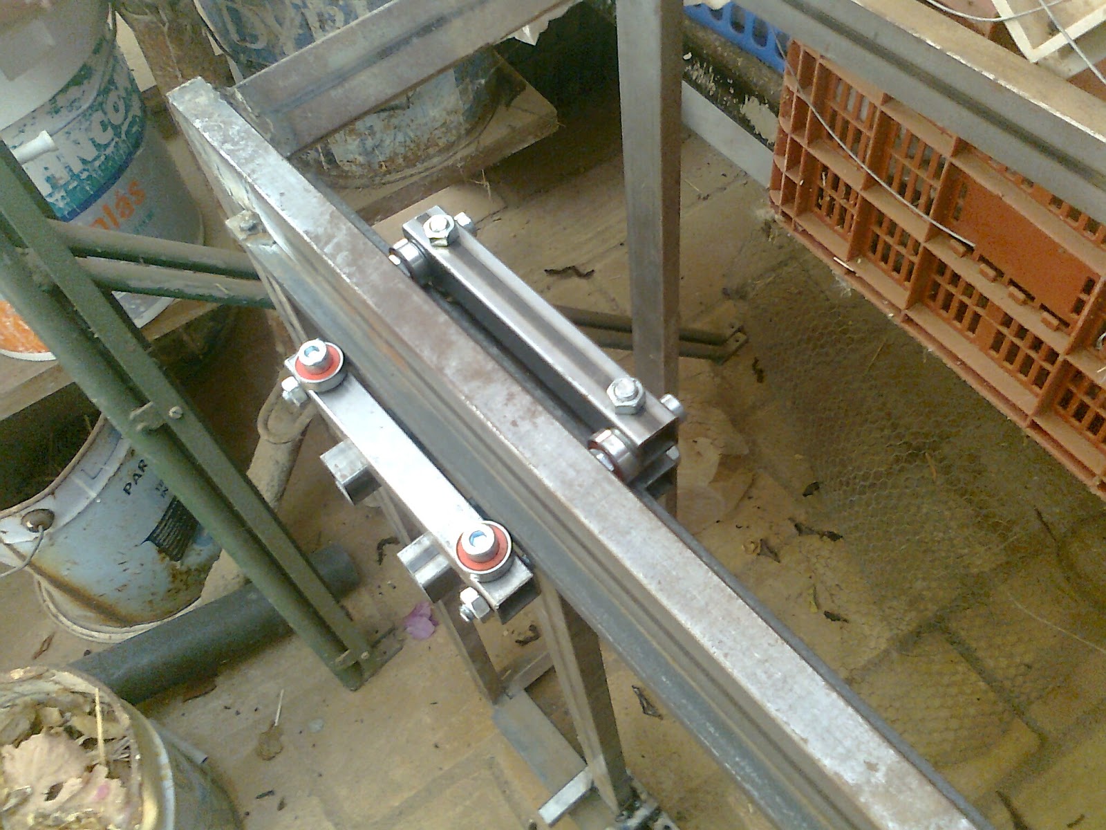
Like I said in my early post the dimensions of my linear guide forced me to make a small change  to be able to properly clamp the linear guide bearing to the rail.
Here is a couple of self explanatory photos.

Clamp tube

Axis fixed side linear guide block fully mounted
Has you can see, the this forms a claw like bearing system that holds the axis in place.
Here are also a couple of shots of the arm in position.

Fixed linear guide mounted in the rail

Fixed linear guide mounted in the rail (down side)
This linear rail slides very well. Since the steel bar (ruler) that acts like the linear rail guide has a orange peel kind surface it's not as smooth has I would like but I believe it will become smoother in time.

Now to the other side of this axis. This will be quite easy and fast. That side will have a much simpler kind of bearing system to allow some level of structural distortion. I count on having it done tomorrow.

Hurray :-) ...

Wednesday, August 28, 2013

Building a CNC - X-Axis - part 1

So here are a couple a shots for the latest developments of my newest CNC machine.
I'm almost finishing the linear rail guide for one of the arms.
Like always some adjustments are needed.

Axis arm with linear guide supports welded


For example the rail guide bar is 8mm thick. That did not allowed me to put the spacers in the threaded rods that hold the bearings. After some evaluation I will need to redo one of the tubes that holds the bearing with an offset so it can clamp to the rail guide, and hold the arm in place (this is the side that locks the arm in the axis the other will be free to avoid misalignment errors).
I'll explain it better in my next post with the finished arm. For now this just shows a general aspect of the CNC horizontal axis arm.


Linear guide partial mount and testing

Expect to finish this arm soon.
Cya...