Electronics DIY blog

DIY is fun and is food for the brain and spirit. Don't be afraid to learn.


Wednesday, October 23, 2013

Building a CNC - Y-Axis - part 2

Here is an update of my CNC building.
Has I stated before I'm doing this in my lunch break. This resumes to 30 min. a day. It's starting to feel more like never ending story... :-P


The second arm (Y-axis) is in place and painted (don't mind the onions on the table....:-P)

CNC with X and Y axis arms mounted
If you remember part 5 of this build, you will notice that this arm is some parts short (the smaller 4x 10cm tubes). Initially I welded them, but if you remember by sketch these were not planed. Because of that if I make de Y-axis in the same manner I did the X-axis the bearing thread system + Stepper will not fit.
So I had to un-weld the hole thing. Even without these, the space to fit these components is very very tight. Let's see if I don't have to do any more changes.

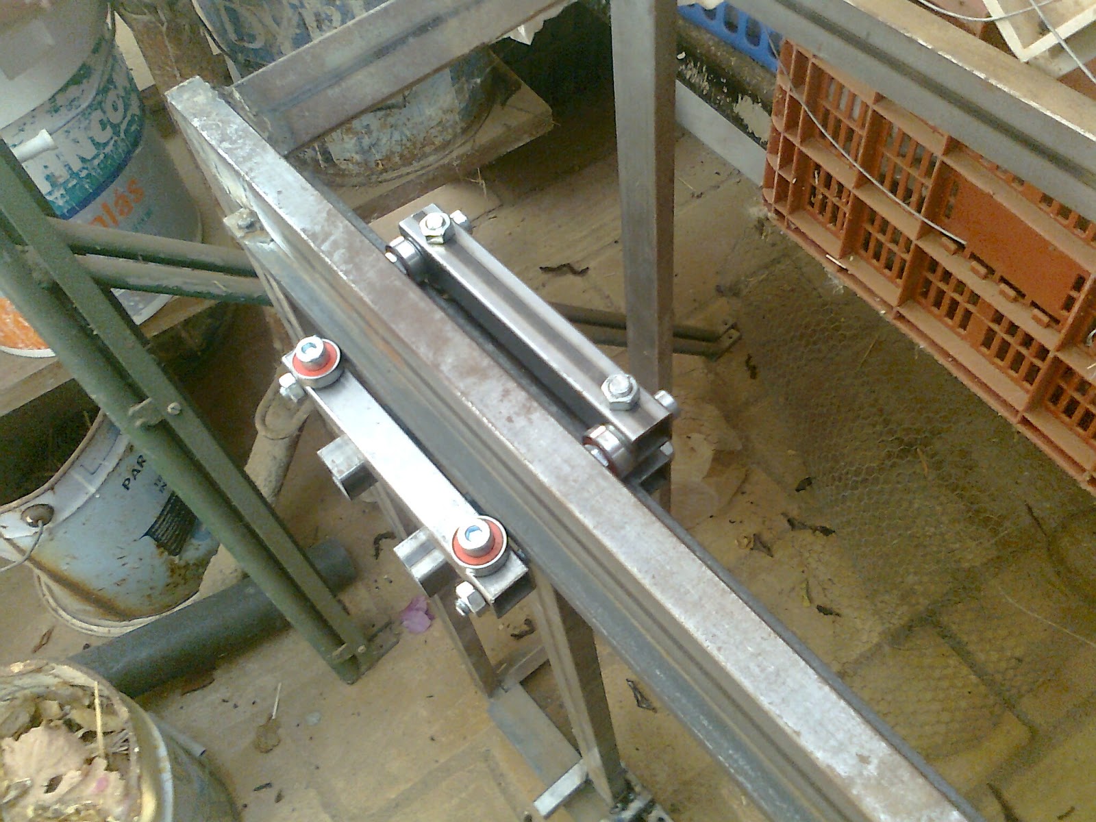
This is the Z-axis linear guide bed mount (the start of it at least). This is actually the second one. I'm building this in the dark (it's all in my head. I've not sketched this or made any pre-measures). Because of the way the bearings and the metal sheet is welded the tube with the off-center holes is the one to be welded. Not the other way around. This is to avoid contact between the bearing and the metal sheet.
Z-axis linear guide bed mount build
It would be best if I just pre draw all in Sketchup to see if it fits. And I probably will. Other wise I will make a lot of mistakes in the way. We will see how it goes.

Fingers crossed...

Sunday, October 13, 2013

SketchUp 3D to GCode plugin

Since the CNC build is very slow due to the lack of time to do any real iron working I've turned into an old quest that was still pending.

A year or so ago I started experimenting with the SketchUp API to have some fun and learn something new.
I've never programmed with Ruby before but my C and C# experience made it pretty easy to learn it in no time.
Then I came to an idea. Make a plugin to convert a SketchUp model directly to GCode.
I debated for a couple of months on the API classes to try to see how I would pull this off. Other things came and I put this project aside.
Early this week I decided to pick this up again. After some intense brainstorming to my self I came with an idea that seemed to work. And it did but the process do scan the model involved boolean operations on SketchUp solids (a hole bunch of them actually) and that is a performance killer.
When I increased resolution SketchUp would stall.

NOOOOO... I found a solution and it was too slow. But then the math concepts I learn in high school came to my head and BAZINGA...

Yeah baby...
What I'm showing here are the results of my SketchUp to GCode converter plugin.

This is in a pre-alpha stage right now, so I'm not going to go in to much detail about this, but I can tell you that it works... :-D

Here are a couple of examples (SketchUp model vs NCPlot- this displays the GCode)

SketchUp modelGCode plot
Example 1
Generated GCode - Dual pass mode
Example 2
Generated GCode - Single pass mode
With some small adaptations this can be used to produce plastic printing GCode too.
I'm developing some more features on this.

Stay tuned...

Thursday, September 26, 2013

Building a CNC - Paint job

Last couple of days I've been sanding and painting the frame and the X-axis to delay corrosion (yes delay...not stop...I don't have the means to do it, but this should suffice since this is going to be indoors). This is the handicap of using regular steel instead of stainless steel for the structure. The good thing is that I will do my hole CNC structure for 40€ worth of steel instead 120€ (or a lot more) in stainless steel.

The painting is quite a tedious task but it's got to be done and that's it.

Here are a couple of shots of the painted pieces.
Sorry for the quality of the pictures but I had almost no day light and my phone does not come with flash.

CNC frame box

CNC X-Axis
Cya...

Tuesday, September 24, 2013

Building a CNC - Y-Axis - part 1

Has I said yesterday today I started building the second arm for my new CNC.

I pre fabricated most of the parts yesterday. So today was about making the remaining parts and assemble them all.

CNC Y-axis arm (pre-fabrication stage)

CNC Y-axis assembled arm (almost completed)

I'm almost finished on this one. I kind of gained some speed because this was almost a question of reproducing a similar X-axis arm with some small changes.

I also painted the X-axis that is completed (forgot to take pictures of that one but I'll show that one tomorrow).

This is going smooth so far but I'll start at work again tomorrow so I'll be back to 20-30 min. construction frames in my lunch time. :-(

Let's see how it rolls from here.

Monday, September 23, 2013

Building a CNC - X-Axis - part 3

Okay.

After a couple of well deserved vacations I'm burning my last two holidays to try to advance has much has I can on my brand new CNC.

Today I got to pre mount the ball bearing thread and motor so I could weld the supports for the thread blocks.
I all fits very nicelly.
Here is a picture.

Pre aligned transmition thread and stepper motor
This one is almost ready for the paint job to avoid runsting.
I also fabricated almost all the necessary peaces for the other arm so I thing tomorrow I can complete the second arm as well.

Lets see how tomorrow goes.

Thursday, August 29, 2013

Building a CNC - X-Axis - part 2

As promised here is the reference side of the axis full mount.
Like I said in my early post the dimensions of my linear guide forced me to make a small change  to be able to properly clamp the linear guide bearing to the rail.
Here is a couple of self explanatory photos.

Clamp tube

Axis fixed side linear guide block fully mounted
Has you can see, the this forms a claw like bearing system that holds the axis in place.
Here are also a couple of shots of the arm in position.

Fixed linear guide mounted in the rail

Fixed linear guide mounted in the rail (down side)
This linear rail slides very well. Since the steel bar (ruler) that acts like the linear rail guide has a orange peel kind surface it's not as smooth has I would like but I believe it will become smoother in time.

Now to the other side of this axis. This will be quite easy and fast. That side will have a much simpler kind of bearing system to allow some level of structural distortion. I count on having it done tomorrow.

Hurray :-) ...

Wednesday, August 28, 2013

Building a CNC - X-Axis - part 1

So here are a couple a shots for the latest developments of my newest CNC machine.
I'm almost finishing the linear rail guide for one of the arms.
Like always some adjustments are needed.

Axis arm with linear guide supports welded


For example the rail guide bar is 8mm thick. That did not allowed me to put the spacers in the threaded rods that hold the bearings. After some evaluation I will need to redo one of the tubes that holds the bearing with an offset so it can clamp to the rail guide, and hold the arm in place (this is the side that locks the arm in the axis the other will be free to avoid misalignment errors).
I'll explain it better in my next post with the finished arm. For now this just shows a general aspect of the CNC horizontal axis arm.


Linear guide partial mount and testing

Expect to finish this arm soon.
Cya...