Electronics DIY blog

DIY is fun and is food for the brain and spirit. Don't be afraid to learn.


Saturday, July 28, 2012

Wah Wah Mods analisys


A brief history


A couple of years ago I (re)started my guitar playing only to put it aside (dam Battlefield :-P). In that intense rebirth of the guitar passion a acquired a couple of guitar pedals and was even building one of my one.
One of the pedals I bought was a Wah Wah Dunlop GCB 95 pedal with the clear mission of modding the hell out of it.
I never even got it out of the box until recently...lol.
Since I'm into a slow comeback to the electronics field I decided to resume this small project.

The Wah FX


I’m not going to explain how the Wah filter works. You can read it in this nice article, but in resume it’s a low pass filter with a peak on the cut-off zone of the response frequency curve (bode diagram). This reproduces somewhat a kind of vocalization of a “wwaaahhh” sound.
The wah circuit is pretty much the same across all pedals, with slight component variations. It uses a kind of LC filter with a circuit that reproduces a variable capacitor (what makes the filter move forward and backward is this C variation).

Here are some pictures of my GCB 95 circuit board (this is the I version and I believe the latest).

PCB front

PCB back

PCB overlay


The Mods


There are a lot of mods on the web so I decided to analyse them before grabbing the iron.


Here are the more popular:


True bypass mod
Vocal mod
Gain and volume mod
Mid range mod
Sweep range mod

Here are other not so popular:


FatWah mod
Transistor mod
Buffer mod


I’m using LTSpice to simulate de circuit. I’ll be basically be looking at the bode diagram (frequency response) of the circuit. I will not show how the mods are done since you can Google it. There's tones of articles explaining what to do. Next I'll present my findings.

The sound changers


Note: All the following diagrams will be present in relation to the original circuit. This means all the mods a showed alone (one at the time). At the end I'll combine the ones I'll most probably implement. All the simulations where done with the pedal value at one of the ends (heel down - the woo part of the wah sound).

True Bypass (Must have or not depends on you)


This actually is the only I did not simulate. It made some confusion in my mind for the first 2 minutes but after reading this article it all became clear.
Since the signal is not totally disconnected/separated (just the output is routed via a SPDT) you will end up with and filter in the way of guitar signal. That filter produces the effect known as “Tone-sucking”. Basically it filters a portion of the original sound muting some of the frequency components of the sound (usually the low and/or high end of the signal’s frequency).

The solution?

Install a good input buffer or true bypass the signal.
Input buffering resides in putting a high/input and low/output impedance between the signal to allow the effect circuit to draw more current from an outside source and spare the weak signal from the guitar. This is applied not only for isolation of circuitry but also to “give new life” to the original signal, when this runs through long cables (the longer the cable the more resistance exists which makes the signal weaker). See good buffers here (JFET are my favourite It makes the guitar very alive).
True bypass is just that The signal is completely shut of from the effect pedal, by input and output routing. There are several articles about doing this, some removing the input buffer and other keeping it. I chose to keep it because of the next mod.
So this is one I should do.


The FatWah (I’m pretty sure it’s a must have)


This is not very known and probably one of the most dramatically changing mods for wah pedals (from an analytical point of view), strangely not mentioned in many mod articles probably because it requires the buffer stage used in the GCB 95(luck me :-D).
First lets take a look at the original frequency response of my GCB 95.


Original GCB 95 bode diagram

As you can see the response is very more or less what you expected (if you read the wah explanation article). The only thing odd is the lower end of the frequency seems to be quite low (-16Db @ 110 Hz – A2 note playing a loose 5th string guitar in standard tuning I believe). The peak sits near 440Hz (A4).
Doesn't seem so much like the theoretical wah filter showed in the article right? Actually it's no wonder this happens. When you plug you wah pedal the sound of your guitar gets "thinner". This happens because the lower frequency spectrum of the signal is being getting attenuated.


So what does the Fatwah does to the signal. Lets look.

FatWah mod bode diagram

Amazing!! The lower frequency range got a nice bost. The down side (from the graphical analysis) is that the "fatness" came at the cost of some vocal strength of the wah due to the reduction in the Q.

never the less the sound should become much more "full".


The vocal mod (also a must have)

Vocal mod bode diagram

This mod changes the Q of the filter making the "hump" of the signal more pronounced. This makes the wah more vocal.

The mid range mod (already factory available)


I will not apply this one for a single reason. It's already in the GCB 95. Changes the Q less then the vocal mod but is not negligible. The wave signal change is similar to the vocal mod but less strong.

The sweep range mod (if detuned wah or instrument adapting)


This actually makes the "hump" slide in frequency. This is the tuning point for your wah. I read in a post in a forum that the sweet spot for a wah pedal is between 440Hz (A4) and 1760Hz (A6) (to octaves apart. This may be needed if your wah sounds dull. The inductors mounted on these puppies suffer from large factory tolerance (ranging from 300mH to 650mH). To tune it you can unsolder the inductor, measure it, calculate/simulate the best value for this capacitor and change it (by adding parallel or series to the original if needed). This is also used to change (a higher value) the wah to a bass wah.

The more subtle mods


The transistor mod (a maybe)


I've simulated with a pair of BC109C. This changes the signal slightly. Makes the Q higher but the gain is smaller. Making a smother more vocal wah.

The gain/volume mod (will not do it)

That's it. it makes the signal more stronger. if you don't remove the input buffer it's not needed. Can make the pedal pick up noise.

The output buffer mod


This is a double mod. This mod is designed to make the wah immune to the fuzz pedal which allegedly kills the wah effect. I have not given this subject much study (the big why) since I'm not a fuzz man my self. This supposedly suppresses the need of an input buffer (I'll be keeping mine for the FatWah mhuahahahah). If a JFET buffer is performed the changes to the sound will be minimal. The output will be something like output of the signal without the buffer multiplied by a 0.98-0.95 gain (will lose around 2-5% in volume).

My Mod selection


Applying the FatWah + Vocal + Middle (already present) I'll get this


My selected mods bode diagram

Seems a lot like the theoretical wah doesn't it? ;-P

Will give it a try and post the results later.

Note: There's also the fasel red/yellow mod. But I'll get to it in a later post.

Cya next time.


Monday, July 23, 2012

CNC frame design considerations

The real challenge in building a CNC is to choose right type of CNC for the desired task. Remember something. The CNC will (a homemade low cost at least) not respond well to every situation. It will be good for the main type of work it was created for and be poor for almost everything else.
The lower priorities might change from builder to builder but the main goals are (in this order):
1-Rigidity
2-Light Weight
3-Vibration tolerance
4-Size efficiency

After building my CNC I ended up getting a CNC with:
1-Light Weight
2-Size efficiency
9-Vibration tolerance
10-Rigidity

In other words my CNC sucks big time lol. It will allow me to do very, very light milling or plastic printing and that’s it. My previous MDF CNC was more stiff than this one although it had other kinds of defects, like to many places where some degree of detuning was induced by vibration.
Despite all defects my CNC is very light weight. The frame itself is about 1/3 of the total weight (the rest is from the lead screw system and motors). Here is a 3D sketch of my machine.

I’ve learned this the hard way: IF YOU DON’T PLAN AHEAD EVERYTHING YOU WILL SPEND ALOT OF MONEY FIXING AND REBUILD THE CNC.
So what are my advices to build a CNC:
- What is the purpose of the CNC and what kind of materials are you going to work?
-Think this through it will influence the whole design. What’s the maximum size of the machine, the material it’s made of, etc…The harder and heavier the material you are planning to work the more important rigidity becomes. The bigger the volume of the biggest piece of material you intend to work more efficient the area of work the machine has to be and of course the harder the rigidity is to achieve.
-There are different typologies of CNC. The movable/fixed part (gantry, bed), type axis of support (fully, partial). If you’re not trying to reinvent the wheel check existing CNC plans (JGRO, and others) for references. My constant decision changing during the execution did not helped the final result. There are advantages/tradeoffs in every single option. Google-it, read learn.
Resuming the more popular solutions:
  • Small milling jobs, and/or lightweight materials, with very high precision can be done in a movable bed CNC (X axis only). It’s quite easy to build to. Nice rigidity.
  • Larger parts, and/or heavy materials call for a movable gantry with partial/fully supported approach. Rigidity harder to achieve.
  • For very lightweight materials and very small jobs and small machine size consider a X and Y movable bed design. This design is more sensible to alignment issues.
From my research and trial/fail experience the Tweaky CNC seems to be a good starting point. The way the frame was designed seems to assure a good compromise between all factors and most situations above.

What are the available raw materials available to you?
For me this was a major setback. I don’t have access to extruded aluminum or steel profiles (like the T-slot). So I had to make everything from very basic hardware, that allied to my weak experience made a poor machine.
Budget?
Don’t fool yourself. It will be expensive no matter what. But it can be more or less expensive after all the design considerations taken.
Approach?
Draw, measure, draw again measure, check for flaws, measure and draw some more. PLAN PLAN PLAN. To keep the costs down plan the whole machine before building. This will reduce mistakes and unforeseen mistakes (that will surely happen in custom made designs).

This is a learning adventure. You will become better. Don’t be afraid to fail (and you will fail), but be smart (smarter then I was lolol). Research a lot before committing. It’s very hard to undo a poor decision, once the ball is rolling.

Here are some usefull references to start with:
CNC Basics
Linear Motion Ideas
CNC Forums
Free CNC Control Software
Self Replicating CNC Project
DIY CNC (one of the many exemples in the WWW)

Hope this helps.

Tuesday, June 12, 2012

CNC Control Box - Part 2

In the previous part I showed how I arranged the electronics for the CNC stepper motors inside a nice and very practical PC case.

I'm now in the process of attaching a plug-panel to easily attach/detach the motors from the control unit.


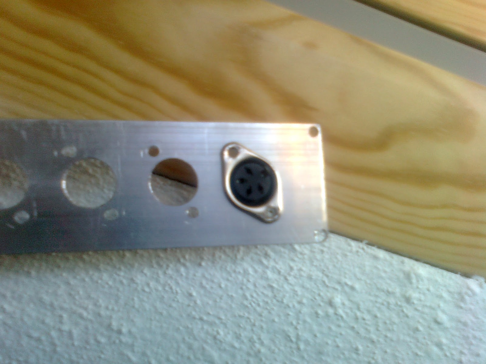
For this I’m using 4-pin DIN panel connectors.

Custom made connector front panel
4-pin DIN panel connector
For me the best spot to place the panel is right in the front of the PC case where the CD-ROM drive should be. I’m using an piece of aluminium (bought an 1000x25x2,5mm stripe of aluminium) that was cut to form the front plate that I’ve cut and drilled to fit the panel connectors.

After I riveted the aluminium plate in the case all that is left I to solder the wires and rivet the connectors to the plate, but you can get the general idea.

Check it out. ;-)


Riveted front panel
Almost finished box


Wednesday, May 23, 2012

ATTEN 858D Repair


Yesterday I decided to repair my ATTEN 858D air gun.

This is a cheap chinese hot air gun to solder/rework pcb boards with smd components.
Disassembled air gun (broke pins place)
The first time I use it got broken. This hot air gun comes with 3 tips to focus the air flow that get jammed very easily. While trying to remove one of those tips I 've broken two plastic pins that hold the resistive part of the gun in place (signaled in green in the pic). The broken plastic pins made the resistance stand floppy and potentially slide out the plastic holder.

Refractory glue for fireplaces
 
Man, that day I even chipped my tooth trying to remove the tip in desperation. Since then I've never inserted those tips to the end, instead I just let them sit on the edge of the gun.

So how do you repair a hot gun that reaches temps well above 400ºC?? Some special glue must come in hand for sure. The answer: Refractory glue used in fireplaces and stoves.

The one I used resists up to 1500ºC. More then enough.
 

Standart PC case screw

The idea was simple. replace the plastic pins with to screws (those used in CD-rom drives or disks to fix the drive in the case are fine). I've started by dremel the remains of the old pins and dig a little deeper to make a bed where the screw head would rest in place (alignment) with the holes in the resistance of the gun. Then I applied the retractile glue in the void ring where the resistance rests. I've made it slightly higher so this ring of glue could work as a clamp. If too much glue is applied I would then remove the excesses with the dremel tool.As you can see the glue filled the ring completely. After trimming this ring to make a tight fit I've screwed everything in place.
 

Glued screw to the resistence support

Make sure the 12 hours of curing are respected (I didn't and the glue broke near the screw, and had to (re)glue them).

After that the resistance was tight in the holder and didn't felt flimsy any more.

Hurray ;-)

Tuesday, May 15, 2012

CNC Control Box - Part 1

Control box (pre)wiring
This will be the control box for my CNC. I bought the kit from Keling Inc. on e-Bay, with the NEMA 34 steppers. The KL-4030 drivers will control the stepper motors in a 1/4 or 1/8 micro stepping configuration. It will all be housed in an old PC case.


Control box wiring final
With a resolution of 1.8 degrees per step (for an 1/8 micro stepping) will allow about 1600 pulse steps per revolution. The motors will by their hand be coupled to a RM1605 ball bearing screw. This means that every pulse the driver receives the axis will travel about 0.003125mm.

The 1/4 or 1/8 micro stepping will be determined by the amount of vibration caused by the motors.

Micro stepping trades torque for vibration and smoothness and even more important trades resolution for accuracy. Make notice I did not mentioned precision because the loss of torque can affect the ability to make the structure move and the motor can actually skid under the force of the unwilling linear motion system. And micro stepping is a real torque sucker. Check this article to see what I’m talking about.

Next will be the wiring of the steppers to the control and testing the micro stepping configuration.

Wednesday, May 9, 2012

The begining


I decided to start this blog to share some of my ideias and home projects. I usually don't like to waist a lot of time writing but I feel that I have to return some "brainstroming" to the web cloud.

The ideia is to share some of the sucesses and failures (there's nothing like a bad project to teach a leason or two), so that maybe somebody may take advantage of it.

Hope to write soon.